PrajnaEdge
A curiosphere for curious minds who want to understand, experiment with, and experience technology.

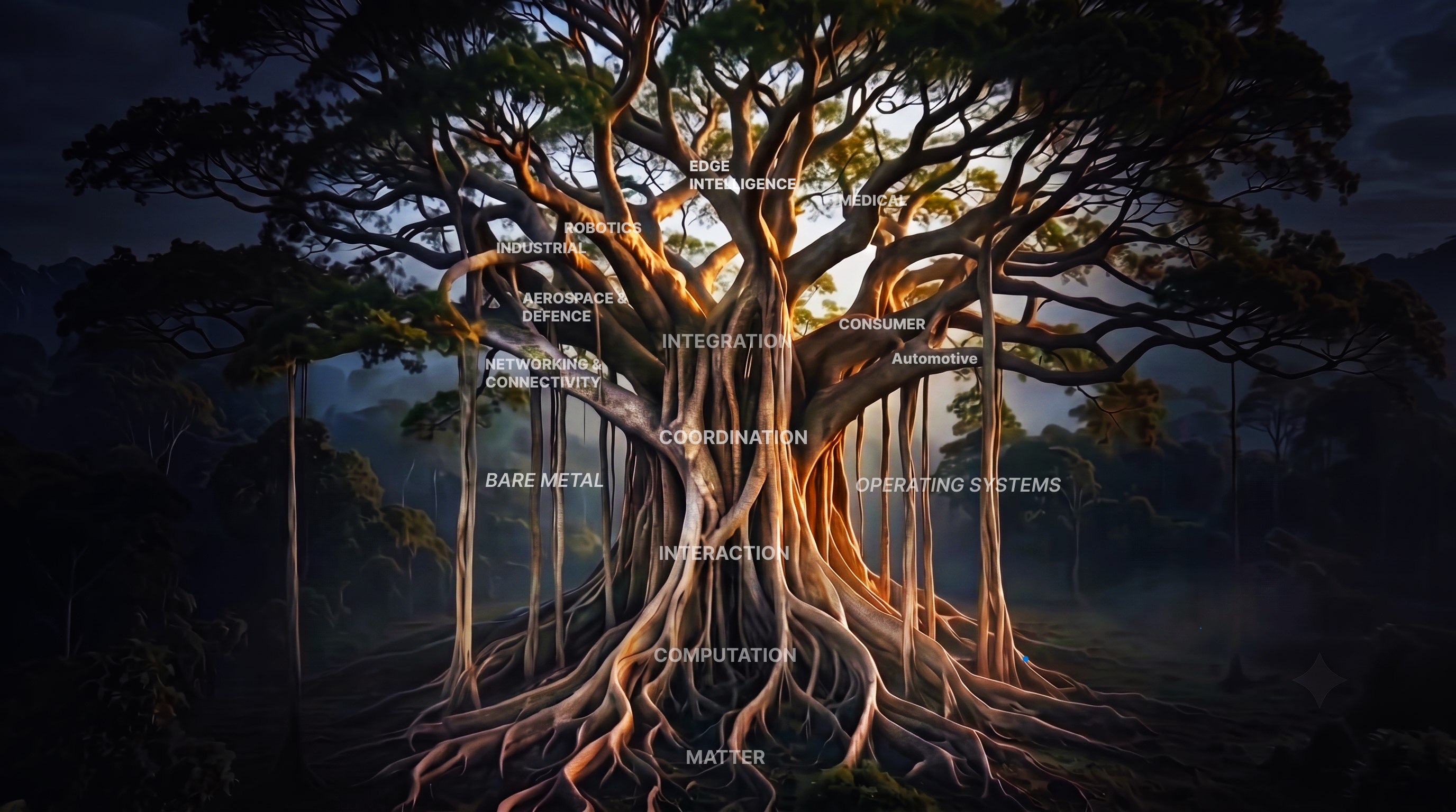
Technology is a system of connections.

Modern technology is built from layers that continuously interact with one another. At the physical level, electronic devices transform electrical signals into digital information. Digital logic turns that information into computation, while processors, memory and communication interfaces provide the machinery needed to execute instructions and move data. As these components become part of embedded systems, they begin to interact with the physical world through sensors, controllers, actuators and real-time software.

But computation does not exist in isolation. Operating systems coordinate hardware and software, firmware gives specialized machines their behaviour, and communication protocols allow independent systems to exchange information. At the same time, machine learning is moving beyond the cloud into edge and on-device systems, where models must operate within real constraints such as memory, processing power, latency and energy consumption.

PrajnaEdge explores these connections as one continuous technology landscape — and takes them beyond explanation. From computing foundations and embedded systems to intelligent machines and edge AI, ideas can be understood, experimented with, and eventually turned into technology that can be experienced in the real world.

To continue exploring
Products

Technology, made tangible.

PrajnaEdge products and technology experiences are currently in development.
In Development

Playground

Experiment with intelligence beyond the cloud.

AI inference performed closer to where data is generated — optimizing model representation to reduce latency, memory footprint, and bandwidth requirements.
Cloud AI Coming Soon

Model Training & Representation

Explore how neural networks learn representations from data before compression and deployment. Future experiments will allow adjusting learning parameters—such as learning rate, epoch counts, and batch sizes—to observe loss trajectories and decision boundaries.

Edge AI Computer Vision

Image Classification

Can this image classifier maintain its intelligence while becoming small enough for the edge?

On-device AI AI-Thinker ESP32-CAM

On-device Image Classification

Run a fully quantized INT8 image-classification model directly on embedded hardware.

Edge AI Playground

Image Classification

Can this image classifier maintain its intelligence while becoming small enough for the edge?

Choose an image

Upload an image
Supports JPG, JPEG, PNG
This classifier recognizes only Apple, Banana, and Orange. Other objects may be incorrectly classified as one of these classes.

Choose the model

Model size
4.91 MiB
Largest activation
~625 KiB
Test accuracy
99.11%
Measured model accuracy
Your image is processed locally in your browser.
On-device AI · Inference

On-device Image Classification

Run a fully quantized INT8 image-classification model directly on embedded hardware.

This experiment investigates preparing a compact INT8 TensorFlow Lite model for direct inference on resource-constrained embedded hardware. The model uses the same CNN architecture as the Edge AI exploration, converted to a full INT8 representation to classify three classes: Apple, Banana, and Orange.

Model size
1.23 MiB
INT8 quantized weights
Model accuracy
99.11%
Measured test accuracy
Target hardware
AI-Thinker ESP32-CAM
Embedded microcontroller target

Explore the ideas, systems and connections that shape technology — choose any node to begin your journey.

PrajnaEdge Navigation Tree
Embedded Systems Tree
View Books →
PrajnaEdge Library

PrajnaEdge Library

Practical guides to embedded systems and engineering.

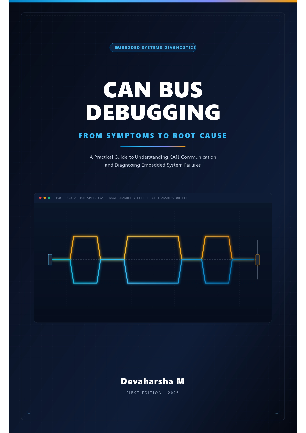
CAN Bus Debugging: From Symptoms to Root Cause Book Cover
Automotive · Embedded Protocol Debugging

CAN Bus Debugging: From Symptoms to Root Cause

  • Select
  • United States
  • United Kingdom
  • Germany
  • France
  • Spain
  • Italy
  • Netherlands
  • Japan
  • Brazil
  • Canada
  • Mexico
  • Australia
  • India

Edge AI Demonstrations

Deploying neural networks and intelligent decision loops on raw silicon targets.

Sort:
Coordination

The Architecture of Time

How machines learned to measure cycles, divide frequencies, and keep promises.

TimersPrescalersPWMCompare MatchInput CaptureReal-Time Systems

1. The Illusion of Speed

In our earlier explorations, we watched systems learn to speak. UART established timing contracts, SPI synchronized clocks, and I2C/CAN introduced bus sharing. Yet, all communication protocols and computational structures share an underlying assumption: they assume the existence of structured, reliable time.

How does software wait? The most naive approach is a busy-wait delay loop:

for(volatile int i = 0; i < 100000; i++);

This simple loop runs on a test bench, but collapses in a real-world system. First, it is entirely clock-frequency dependent: if the microcontroller switches from an 8 MHz internal RC oscillator to a 168 MHz external crystal, the delay shrinks to a fraction of its intended duration. Second, if you enable compiler optimizations (such as -O3), the compiler may strip the empty loop entirely. Third, if an interrupt service routine (ISR) fires during the loop, the CPU suspends execution to handle the event, stretching the delay unpredictably. Software alone cannot keep temporal promises.

2. The Hardware Counter

To keep time reliably, the CPU must delegate the task to dedicated hardware: the timer. At its simplest, a timer is an independent hardware block consisting of a clock oscillator feeding a digital register called the Counter (CNT).

On every tick of the clock, the counter register increments. Because this incrementing happens in hardware, it is completely independent of CPU execution. The CPU can be performing complex arithmetic, waiting for an interrupt, or even resting in a low-power sleep state; the hardware counter increments steadily in the background, counting clock cycles to track elapsed time.

3. Prescalers: Division of Labor

Directly clocking the counter register quickly reveals a physical limitation: frequency. Suppose our microcontroller runs at 84 MHz, and we use a 16-bit counter register (which can hold values from 0 to 65,535).

At 84 million ticks per second, the counter will fill up and wrap back to zero in just 780 microseconds. Measuring a simple 1-second interval would require tracking thousands of wraps in software, consuming CPU cycles and defeating the purpose of hardware timing.

To solve this, timers use a Prescaler (PSC). The prescaler is a programmable frequency divider. If we set the prescaler to 8399, the incoming 84 MHz clock is divided by 8400 (PSC + 1), feeding the counter a slow, manageable 10 kHz signal. The counter now increments once every 100 microseconds, wrapping in a comfortable 6.5 seconds.
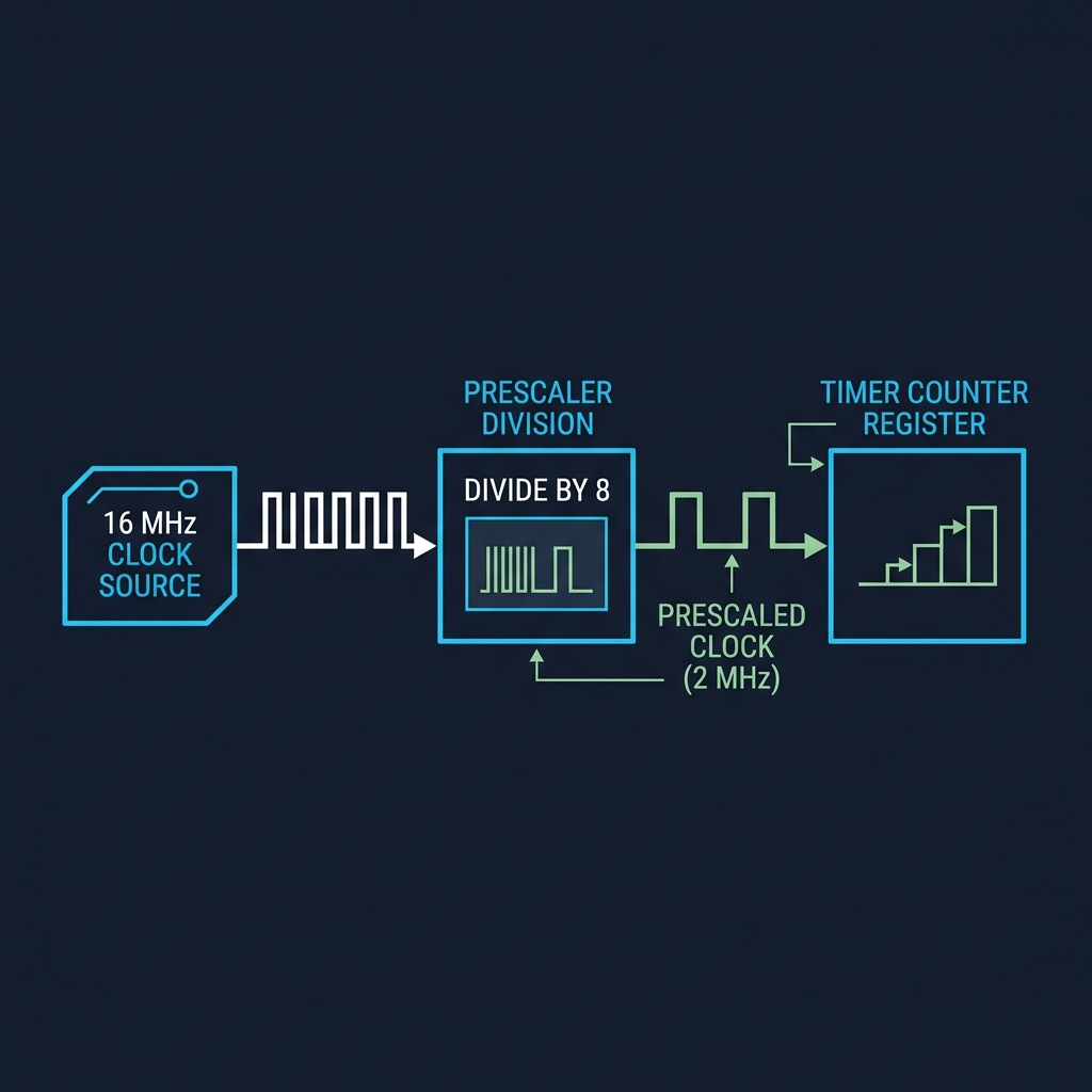
Timer Clock Division: Clock source divided by Prescaler to drive Counter CNT

4. Overflow: The Heartbeat of wrapping

When the counter register counts past its maximum value (or a configured Auto-Reload Register / ARR value), it wraps back to zero. This wraparound is called an Overflow.

The moment an overflow occurs, the timer hardware asserts an Update Interrupt Flag (UIF) and can trigger a CPU interrupt. By adjusting the ARR value, we dictate the exact period of this wraparound. A 10 kHz counter configured to wrap at 10,000 generates an overflow interrupt exactly once every second, creating a deterministic periodic heartbeat.
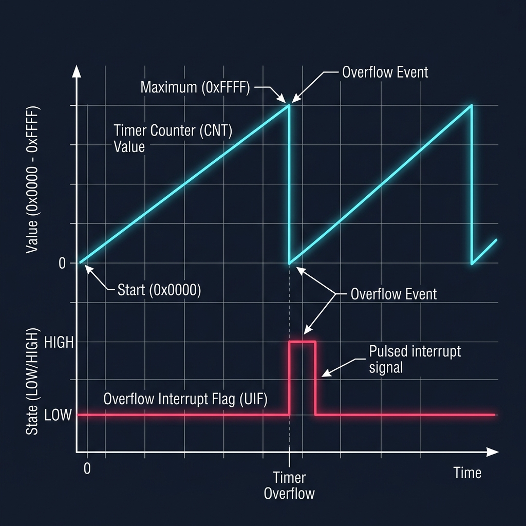
Timer Overflow Sequence showing Counter wrapping at ARR and generating Update Flag

5. Compare Match: Keeping Promises

Periodic overflows are useful, but what if we need events to happen during the count cycle? That is where the Compare Register (CCR) comes in.

The CPU writes a target value to the CCR. The timer's hardware comparator continuously checks: Is CNT == CCR?.

The moment the counter matches the compare register, the timer asserts a Compare Match flag and can toggle an output pin or trigger an event. This allows the system to schedule precise sub-millisecond events without CPU intervention.
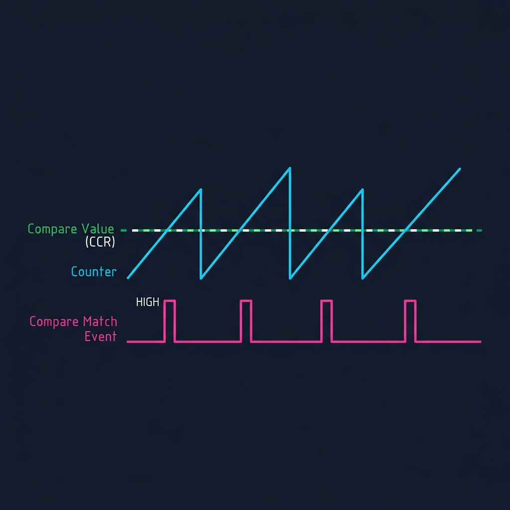
Timer Compare Match Waveform showing Counter intersecting CCR to trigger Match Events

6. Timer Configurator: The Race Against Time

Let's experiment with these core concepts. In the simulator below, configure the clock source, prescaler division, counter size, and compare match values to see how physical frequencies translate into structured temporal events.

7. Pulse Width Modulation: Painting with Time

Compare match logic unlocks a powerful technique: Pulse Width Modulation (PWM). If we configure a timer pin to go HIGH on counter reset (0) and go LOW when the counter matches the Compare Value (CCR), we generate a repeating digital pulse train.

By changing the compare value, we adjust the Duty Cycle—the percentage of the period that the signal is HIGH. By toggling this signal at high frequencies, we can simulate an analog voltage.

A 50% duty cycle on a 3.3V pin outputs 3.3V half the time, averaging to 1.65V. To an LED, this appears as half brightness. To a DC motor, it translates to half speed. Timers allow us to paint analog behaviors onto digital silicon using nothing but time.
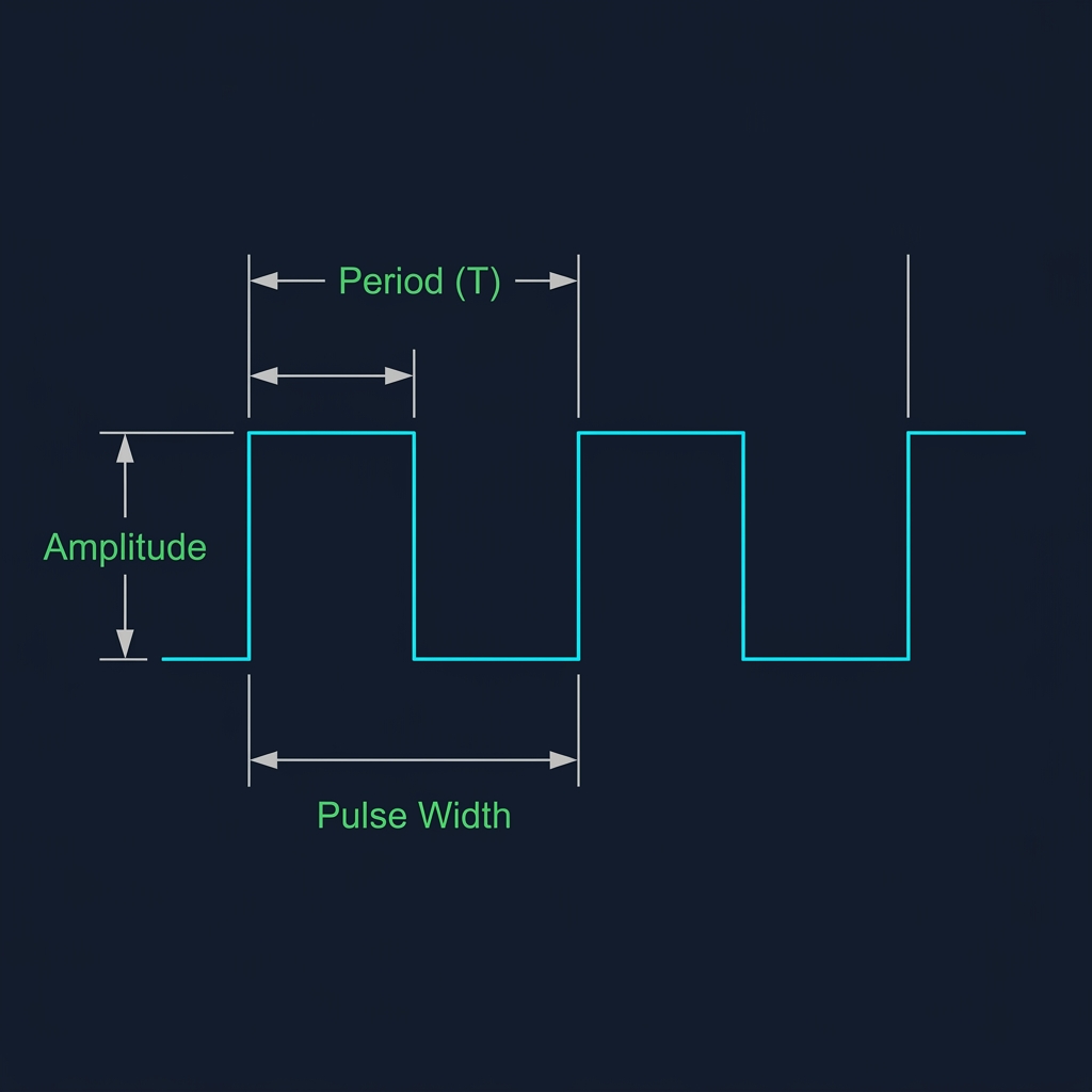
PWM Waveform showing Period, Pulse Width, and Amplitude
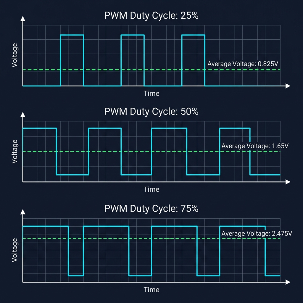
Comparison of 25%, 50%, and 75% Duty Cycles and resulting average voltages

8. PWM Simulator: Painting with Time

Adjust the frequency and duty cycle below to see how pulse widths map directly to average output voltages, controlling LED intensity and motor velocity.

9. Input Capture: Measuring the World

Timers do not just generate waveforms; they can also measure them. This is the role of Input Capture.

Instead of the counter triggering changes on an external pin, external pin transitions (edges) trigger the timer. When a rising edge is detected on an input capture pin, the hardware instantly copies (captures) the current counter value (CNT) into the capture register (CCR). When the falling edge arrives, it captures the value again.

By subtracting the first captured value from the second, the software can measure the exact pulse width of an external signal down to the nanosecond, enabling precise sensor decoding (such as ultrasonic distance sensors or RPM tachometers) with zero CPU polling overhead.
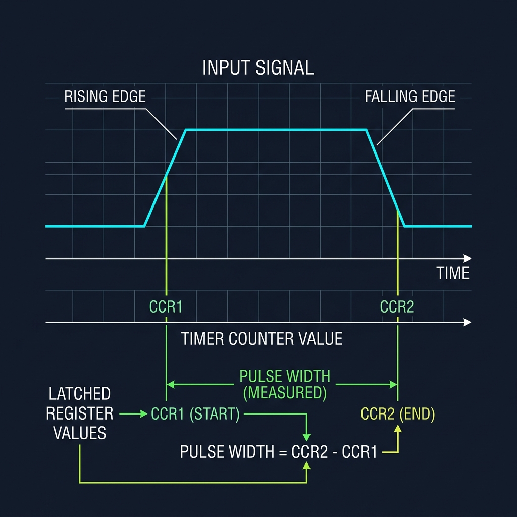
Timer Input Capture timing showing CCR latching at rising/falling edges to measure width

The Foundation of Decision

Communication protocols taught machines how to exchange information. Time taught machines how to coordinate action.

Before a system can observe the world, react to events, or schedule complex work, it must first learn how to measure time itself. With a structured heartbeat established, we can begin exploring how multiple activities are coordinated on a single CPU core.

Time is the canvas upon which coordination is painted. Without a clock, a machine is merely reactive; with one, it becomes purposeful.
System Tree Node Coordination

PrajnaEdge

Engineering concepts you don't just read — you experience.
Founded in 2026.

PrajnaEdge is a technology company exploring the space between understanding technology, experimenting with ideas, and turning them into things that can be experienced.

Our Mission

To make technology easier to explore, deeper to understand, and more exciting to experience.

Our Vision

To build a technology ecosystem where curiosity, experimentation and creation continuously lead to one another.

Where it began

Embedded Systems

PrajnaEdge began with Embedded Systems — exploring the foundations that connect hardware, software and intelligent computation.

The first technology universe is built around that foundation. The journey will expand as new ideas, experiments and products emerge.

PrajnaEdge is a technology company created by Devaharsha Meesarapu.

CREATOR PROFILE

Devaharsha Meesarapu

Embedded Systems • Firmware • Edge AI

I am the engineer behind the design, development, and content of PrajnaEdge. I build low-level systems where code directly controls hardware, bridging the gap between register-level silicon behavior and intelligent edge decision loops.

View Resume →

ABOUT ME

I am an Embedded Firmware Engineer focused on developing software for resource-constrained systems. My experience spans bare-metal firmware, device drivers, microcontroller peripherals, and communication protocols, working across the boundary between hardware and software.

My work has involved microcontroller-based systems, real-time behaviour, hardware interfaces, and communication technologies such as CAN, CAN FD, UART, SPI, and I²C. I am particularly interested in understanding systems from the lowest level upward—from registers and peripherals to intelligent edge systems.

ENGINEERING PHILOSOPHY

Engineering is not just about writing code; it is about managing constraints, timings, and physical hardware characteristics. True mastery of complex systems comes from understanding the interactions across different layers of the stack.

This conviction is why I built PrajnaEdge—to bridge the gap between conceptual theory and direct, register-level physical reality.

CONNECT

LinkedIn → GitHub →

Interactive Career Journey

BTech · ECE

Foundations

Where it all began — understanding the physical layer of computation. Circuits, signals, and systems gave me a mental model of how information moves through hardware.

⬡
Connects to Systems
Understanding circuits directly enables writing firmware that talks to peripherals at the register level.
What it is
BTech in Electronics and Communication
Undergraduate foundation covering analog & digital circuits, signal processing, microprocessors, and communication systems.
CircuitsSignal ProcessingMicroprocessorsVLSI
What I did
Core Engineering Fundamentals
Studied semiconductor physics, digital logic design, and embedded microcontrollers. Built prototypes using 8-bit MCUs.
8051Logic DesignPCB Basics
What I learned
The Hardware Mental Model
Every software abstraction sits on physical reality. Understanding silicon teaches you why timing, power, and noise are first-class engineering problems.
Let's Connect
Interested in embedded systems, AI, or building something meaningful? I'd love to hear from you.
Open to collaborations, research, and interesting engineering conversations.
Help Improve PrajnaEdge
Found something to improve? I'd love to hear your thoughts.

Bare Metal

Software that runs directly on hardware without an operating system.

Applications
↑
Operating Systems
YOU ARE HERE
Bare Metal
Processor
↑
Hardware

"Every embedded application begins long before main()."

Operating Systems

An Operating System manages hardware and software resources so complex applications can work efficiently.

Applications
↑
YOU ARE HERE
Operating Systems
Bare Metal
↑
Processor
↑
Hardware

"When one loop is no longer enough to carry the burden."

← Return to Systems Tree
Select Domain
Explore application domains branching from the Systems Tree
Automotive
Aerospace & Defence
Consumer
Embedded AI
Industrial
Medical
Multimedia
Network & Connectivity
Robotics
Explore Active Systems Tree →
← Return to Systems Tree
Select Depth
Examine computation through architectural depth layers
Architecture
Controller
Digital
Programming
Processor
Explore Processors → Explore Controllers →

Support PrajnaEdge

PrajnaEdge is an independent education platform built to make knowledge freely accessible.

If you find PrajnaEdge useful, you can support its continued development.

Your support helps fund the time, tools, infrastructure, and experimentation that go into building and maintaining PrajnaEdge.

Select Region
Select Amount
Select an amount to support PrajnaEdge.