PrajnaEdge
A curiosphere for curious minds who want to understand, experiment with, and experience technology.

Technology is a system of connections.

Modern technology is built from layers that continuously interact with one another. At the physical level, electronic devices transform electrical signals into digital information. Digital logic turns that information into computation, while processors, memory and communication interfaces provide the machinery needed to execute instructions and move data. As these components become part of embedded systems, they begin to interact with the physical world through sensors, controllers, actuators and real-time software.

But computation does not exist in isolation. Operating systems coordinate hardware and software, firmware gives specialized machines their behaviour, and communication protocols allow independent systems to exchange information. At the same time, machine learning is moving beyond the cloud into edge and on-device systems, where models must operate within real constraints such as memory, processing power, latency and energy consumption.

PrajnaEdge explores these connections as one continuous technology landscape — and takes them beyond explanation. From computing foundations and embedded systems to intelligent machines and edge AI, ideas can be understood, experimented with, and eventually turned into technology that can be experienced in the real world.

To continue exploring
Products

Technology, made tangible.

PrajnaEdge products and technology experiences are currently in development.
In Development

Playground

Experiment with intelligence beyond the cloud.

AI inference performed closer to where data is generated — optimizing model representation to reduce latency, memory footprint, and bandwidth requirements.
Cloud AI Coming Soon

Model Training & Representation

Explore how neural networks learn representations from data before compression and deployment. Future experiments will allow adjusting learning parameters—such as learning rate, epoch counts, and batch sizes—to observe loss trajectories and decision boundaries.

Edge AI Computer Vision

Image Classification

Can this image classifier maintain its intelligence while becoming small enough for the edge?

On-device AI AI-Thinker ESP32-CAM

On-device Image Classification

Run a fully quantized INT8 image-classification model directly on embedded hardware.

Edge AI Playground

Image Classification

Can this image classifier maintain its intelligence while becoming small enough for the edge?

Choose an image

Upload an image
Supports JPG, JPEG, PNG
This classifier recognizes only Apple, Banana, and Orange. Other objects may be incorrectly classified as one of these classes.

Choose the model

Model size
4.91 MiB
Largest activation
~625 KiB
Test accuracy
99.11%
Measured model accuracy
Your image is processed locally in your browser.
On-device AI · Inference

On-device Image Classification

Run a fully quantized INT8 image-classification model directly on embedded hardware.

This experiment investigates preparing a compact INT8 TensorFlow Lite model for direct inference on resource-constrained embedded hardware. The model uses the same CNN architecture as the Edge AI exploration, converted to a full INT8 representation to classify three classes: Apple, Banana, and Orange.

Model size
1.23 MiB
INT8 quantized weights
Model accuracy
99.11%
Measured test accuracy
Target hardware
AI-Thinker ESP32-CAM
Embedded microcontroller target

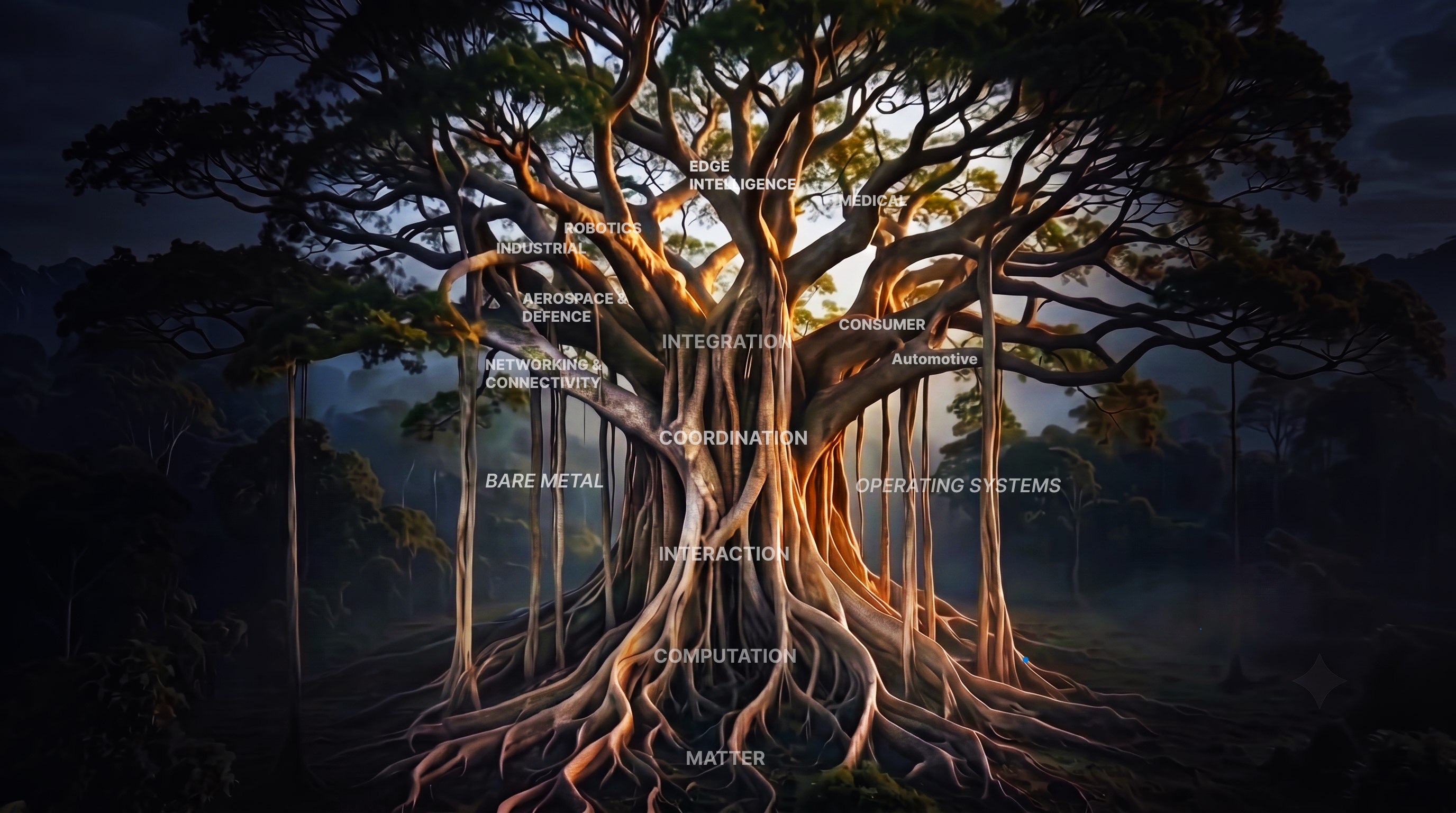
Explore the ideas, systems and connections that shape technology — choose any node to begin your journey.

PrajnaEdge Navigation Tree
Embedded Systems Tree
View Books →
PrajnaEdge Library

PrajnaEdge Library

Practical guides to embedded systems and engineering.

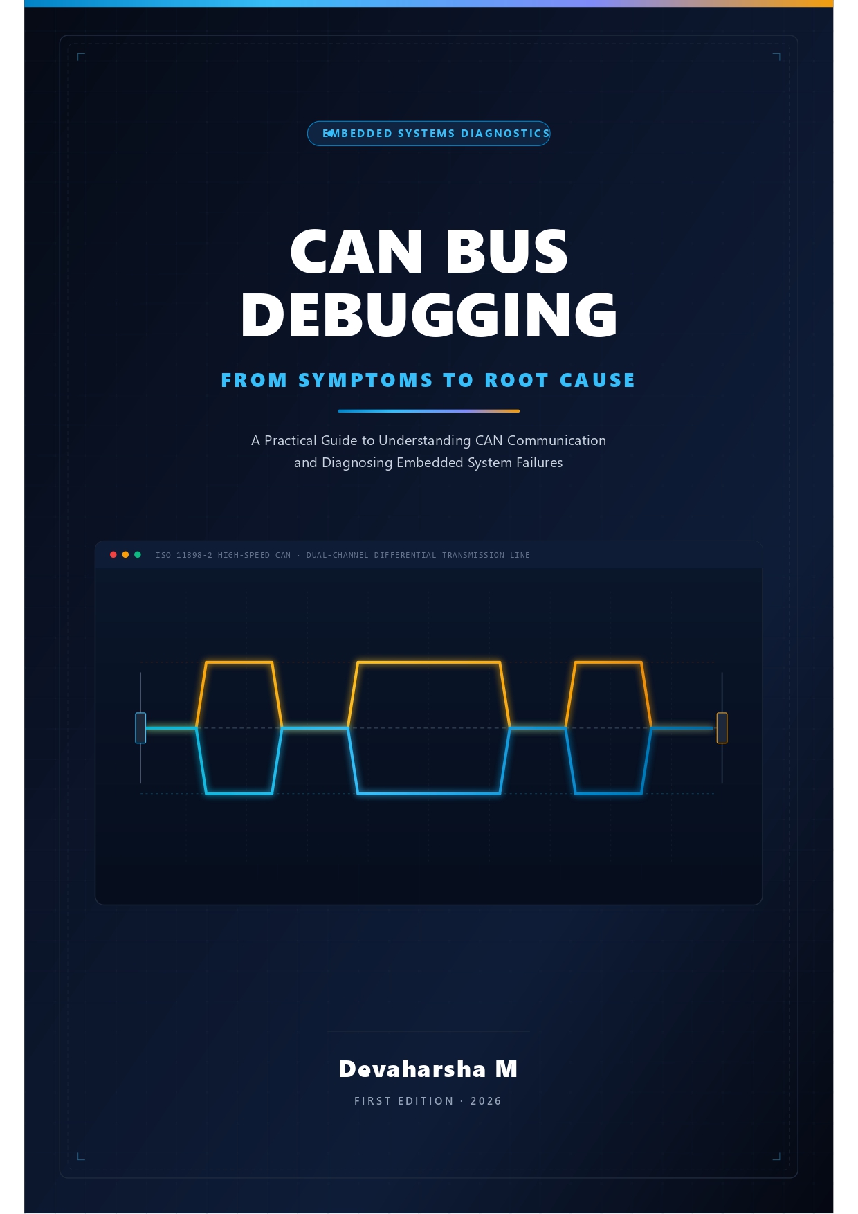
CAN Bus Debugging: From Symptoms to Root Cause Book Cover
Automotive · Embedded Protocol Debugging

CAN Bus Debugging: From Symptoms to Root Cause

  • Select
  • United States
  • United Kingdom
  • Germany
  • France
  • Spain
  • Italy
  • Netherlands
  • Japan
  • Brazil
  • Canada
  • Mexico
  • Australia
  • India

Edge AI Demonstrations

Deploying neural networks and intelligent decision loops on raw silicon targets.

Sort:
Interaction

I2C: The Shared Conversation

How open-drain logic and addressing solved the pin inflation crisis of SPI.

I2CSerial ProtocolsOpen DrainArbitrationEmbedded Systems

1. The SPI Pin Crisis

SPI unlocked extreme communication speeds by sharing a clock, but it introduced a severe hardware bottleneck: pin inflation. Because SPI has no addressing system, the master must use a dedicated Chip Select (CS) pin for every single peripheral on the bus. If you connect five sensors, you need five separate CS pins. If you scale to ten devices, your microcontroller's GPIO lines are consumed entirely by chip selection.

This physical routing nightmare forced engineers to re-evaluate the bus architecture. They needed a protocol that preserved the benefits of a synchronous clock but allowed dozens of devices to share the exact same physical wires without a forest of chip select lines. The solution was the Inter-Integrated Circuit (I2C) protocol.

2. Shared Wires: The Two-Line Compromise

I2C makes a radical design trade-off. It discards the four-wire, point-to-point architecture of SPI in favor of a strictly shared, two-wire bus: SDA (Serial Data) and SCL (Serial Clock). Every device on the bus connects to these same two traces.

By shrinking the bus to two wires, I2C eliminates the physical pin bottleneck. A master can communicate with over a hundred devices using the exact same two pins. However, this simplicity introduces a complex electrical challenge: if multiple devices share the same data and clock lines, how do we prevent them from colliding and burning out their output drivers when one tries to transmit a 1 while another transmits a 0?
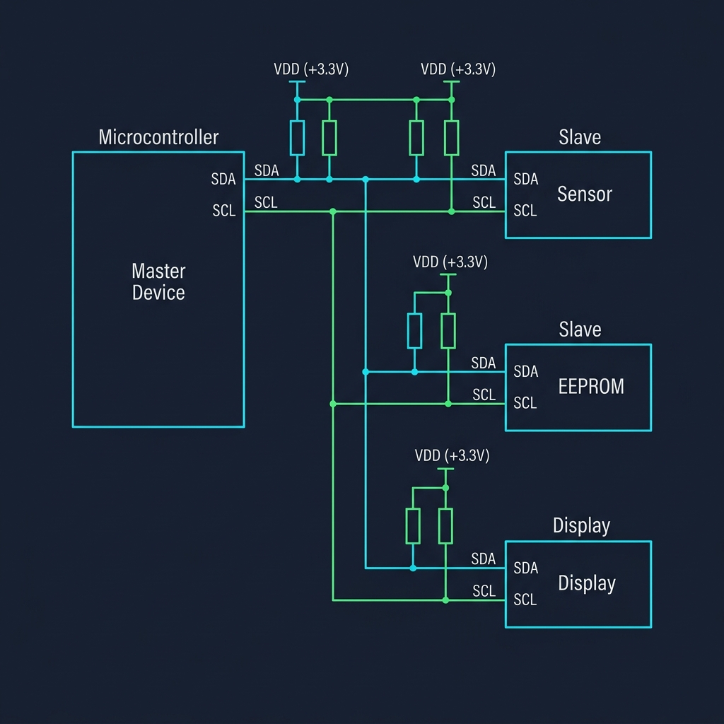
I2C Shared Bus Topology showing Pull-up resistors and multiple slaves

3. The Physics of Open-Drain Buses

In standard push-pull output stages (used in UART and SPI), a device actively drives the line HIGH (connecting it to VCC) or actively drives it LOW (connecting it to GND). If Device A drives HIGH while Device B drives LOW on a shared wire, a low-resistance path is created directly from VCC to GND. This causes a short circuit, excessive current draw, heating, and physical damage to the silicon.

To prevent this, I2C uses open-drain (or open-collector) output buffers combined with physical pull-up resistors on both SCL and SDA. In an open-drain buffer, a device can only actively pull the line LOW (turning on an internal NMOS transistor connected to GND). It cannot actively drive the line HIGH; instead, to send a 1, it simply turns off the transistor and lets the line float. The external pull-up resistor then pulls the line HIGH.

This creates a 'wired-AND' logic bus. If any single device pulls the line LOW, the entire line goes LOW. The line only returns HIGH when every single device releases it. Electrical collisions are resolved safely: if two devices write conflicting states, the line simply resolves to LOW, drawing only a safe, limited current through the pull-up resistor.
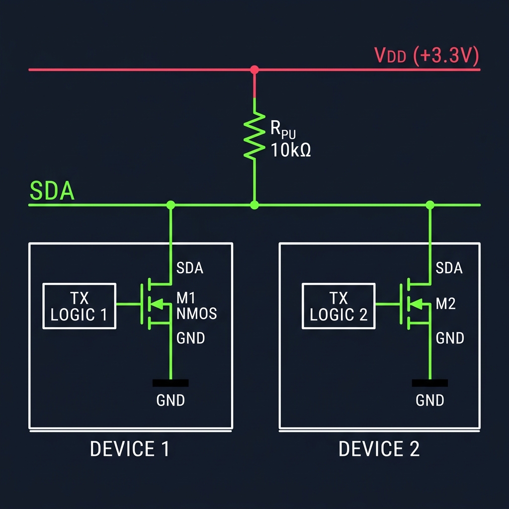
I2C Open-Drain Transistor Circuit Schematic

4. The Syntax of a Shared Wire

Because I2C lacks physical Chip Select lines, the protocol must establish starting boundaries and address routing directly within the two-wire interface. Under normal operation, the SDA line is only allowed to change state when the SCL clock line is LOW. When SCL is HIGH, the data on SDA must remain stable to be sampled.

I2C exploits this stability rule to define START and STOP conditions. A START condition is signaled when SDA transitions from HIGH to LOW while SCL is HIGH. A STOP condition is signaled when SDA transitions from LOW to HIGH while SCL is HIGH. These transitions act as start-of-frame and end-of-frame markers that every peripheral monitors on the bus, resetting their internal receivers to listen for addressing.
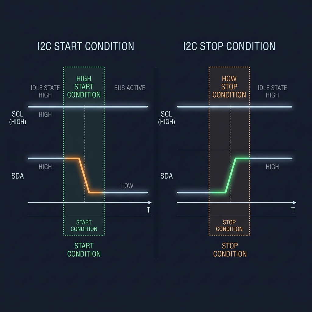
I2C START and STOP Condition Waveforms

5. Software Addressing and Handshaking

Immediately following a START condition, the master transmits a 9-bit address frame. The first 7 bits represent the unique target address of the slave. The 8th bit indicates the transaction direction: Write (0) or Read (1).

The 9th clock cycle is reserved for a hardware handshake: the Acknowledge (ACK) bit. During the 9th clock tick, the master releases the SDA line (letting it float HIGH). The slave device matching the address must actively pull the SDA line LOW. If the slave pulls SDA LOW, it is an ACK—the transaction continues. If the slave is missing, busy, or has crashed, the line remains HIGH (a Not-Acknowledge, or NACK), signaling the master to stop.

6. Slowing the Master: Clock Stretching

SPI is a 'blind' protocol: the master drives SCLK regardless of whether the slave has processed the data. If the slave lags behind, data is lost. I2C solves this flow-control problem using clock stretching.

Although the master normally controls SCL, the open-drain architecture allows a slave to take control. If a slave needs more time to process a byte or fetch sensor readings, it can actively hold the SCL line LOW after the master releases it. The master monitors the SCL line: as long as it senses SCL is LOW, its internal clock generator pauses, freezing the transaction. Only when the slave releases SCL does it float HIGH and the master continues.

7. Polite Arguments: Multi-Master Arbitration

In complex systems, multiple master devices may share the same bus. If two masters assert a START condition simultaneously, I2C uses bus arbitration to resolve conflicts without corrupting data or causing electrical shorts.

Because of the open-drain wired-AND structure, both masters can drive SCL and SDA. As they transmit data bits, each master monitors the actual state of the SDA line. As long as the bus matches the bits they write, they proceed. However, if Master A writes a 1 (releasing SDA) but Master B writes a 0 (pulling SDA LOW), the bus resolves to LOW. Master A, sensing a LOW when it expected a HIGH, realizes another master is active, immediately halts its transmission, releases the bus, and falls back to receiver mode. Master B continues its transaction completely uninterrupted, unaware of the silent victory.
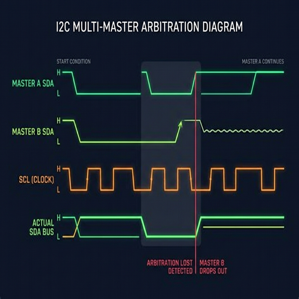
I2C Multi-Master Arbitration Timing Diagram

8. The Threshold of Complexity

Let's review the journey: UART taught us to align clock phases through a timing contract between two nodes. SPI showed us that sharing a physical clock yields speeds orders of magnitude higher at the cost of dedicated wiring. I2C showed us that by using addressing and open-drain physics, we can share the clock and data wires completely, scaling to dozens of devices using only two pins.

Yet I2C has limits. The pull-up resistors create an RC time constant with the parasitic capacitance of the wires: as the bus gets longer or more devices are added, the rising edge of SCL/SDA becomes slow and rounded, limiting speeds (typically 400 kHz to 3.4 MHz) and distances to a few meters. Furthermore, in high-noise environments like automotive engines or industrial floors, common-mode noise can easily flip single-ended logic levels.

When we need to scale to longer distances, high noise immunity, and multi-master robustness without master-slave dependencies, we must look beyond single-ended voltage sharing to differential, arbitrated networks—leading us to the design of the Controller Area Network (CAN).

The Cooperative Bus

I2C stands as a monument to cooperation in hardware. By shifting the selection burden from dedicated copper wires (SPI's CS) to software protocol syntax and open-drain physics, it enables complex inter-chip ecosystems using minimum resources.

It reminds us that communication is not just about driving voltages, but agreeing on when to listen and when to step aside.

On a shared wire, silence is as critical as speech. It is the pull-up resistor that lifts the bus when all devices learn to let go.
System Tree Node Interaction

PrajnaEdge

Engineering concepts you don't just read — you experience.
Founded in 2026.

PrajnaEdge is a technology company exploring the space between understanding technology, experimenting with ideas, and turning them into things that can be experienced.

Our Mission

To make technology easier to explore, deeper to understand, and more exciting to experience.

Our Vision

To build a technology ecosystem where curiosity, experimentation and creation continuously lead to one another.

Where it began

Embedded Systems

PrajnaEdge began with Embedded Systems — exploring the foundations that connect hardware, software and intelligent computation.

The first technology universe is built around that foundation. The journey will expand as new ideas, experiments and products emerge.

PrajnaEdge is a technology company created by Devaharsha Meesarapu.

CREATOR PROFILE

Devaharsha Meesarapu

Embedded Systems • Firmware • Edge AI

I am the engineer behind the design, development, and content of PrajnaEdge. I build low-level systems where code directly controls hardware, bridging the gap between register-level silicon behavior and intelligent edge decision loops.

View Resume →

ABOUT ME

I am an Embedded Firmware Engineer focused on developing software for resource-constrained systems. My experience spans bare-metal firmware, device drivers, microcontroller peripherals, and communication protocols, working across the boundary between hardware and software.

My work has involved microcontroller-based systems, real-time behaviour, hardware interfaces, and communication technologies such as CAN, CAN FD, UART, SPI, and I²C. I am particularly interested in understanding systems from the lowest level upward—from registers and peripherals to intelligent edge systems.

ENGINEERING PHILOSOPHY

Engineering is not just about writing code; it is about managing constraints, timings, and physical hardware characteristics. True mastery of complex systems comes from understanding the interactions across different layers of the stack.

This conviction is why I built PrajnaEdge—to bridge the gap between conceptual theory and direct, register-level physical reality.

CONNECT

LinkedIn → GitHub →

Interactive Career Journey

BTech · ECE

Foundations

Where it all began — understanding the physical layer of computation. Circuits, signals, and systems gave me a mental model of how information moves through hardware.

⬡
Connects to Systems
Understanding circuits directly enables writing firmware that talks to peripherals at the register level.
What it is
BTech in Electronics and Communication
Undergraduate foundation covering analog & digital circuits, signal processing, microprocessors, and communication systems.
CircuitsSignal ProcessingMicroprocessorsVLSI
What I did
Core Engineering Fundamentals
Studied semiconductor physics, digital logic design, and embedded microcontrollers. Built prototypes using 8-bit MCUs.
8051Logic DesignPCB Basics
What I learned
The Hardware Mental Model
Every software abstraction sits on physical reality. Understanding silicon teaches you why timing, power, and noise are first-class engineering problems.
Let's Connect
Interested in embedded systems, AI, or building something meaningful? I'd love to hear from you.
Open to collaborations, research, and interesting engineering conversations.
Help Improve PrajnaEdge
Found something to improve? I'd love to hear your thoughts.

Bare Metal

Software that runs directly on hardware without an operating system.

Applications
↑
Operating Systems
YOU ARE HERE
Bare Metal
Processor
↑
Hardware

"Every embedded application begins long before main()."

Operating Systems

An Operating System manages hardware and software resources so complex applications can work efficiently.

Applications
↑
YOU ARE HERE
Operating Systems
Bare Metal
↑
Processor
↑
Hardware

"When one loop is no longer enough to carry the burden."

← Return to Systems Tree
Select Domain
Explore application domains branching from the Systems Tree
Automotive
Aerospace & Defence
Consumer
Embedded AI
Industrial
Medical
Multimedia
Network & Connectivity
Robotics
Explore Active Systems Tree →
← Return to Systems Tree
Select Depth
Examine computation through architectural depth layers
Architecture
Controller
Digital
Programming
Processor
Explore Processors → Explore Controllers →

Support PrajnaEdge

PrajnaEdge is an independent education platform built to make knowledge freely accessible.

If you find PrajnaEdge useful, you can support its continued development.

Your support helps fund the time, tools, infrastructure, and experimentation that go into building and maintaining PrajnaEdge.

Select Region
Select Amount
Select an amount to support PrajnaEdge.